Cable Segment Impedance |
In the transmission line formalism, the interaction between various conductors in a segment is characterized by cable impedance matrices. The impedance matrices, identified by the symbols C, L, R, and G in Chapter 3 define the relationship between the various wires and shields within a segment of an
MHARNESS® cable, incorporating the effects of the surrounding media. The symbol C stands for the capacitance matrix, L for the inductance matrix, R for the resistance matrix and G for the conductance matrix. The presence of a conductance matrix allows the cable conductors to be immersed in a variety of lossy media. In MHARNESS the impedance matrices are all time independent.For a single conductor segment C, L, R, and G are real numbers. For a segment with n conductors, these entities are n×n matrices. The capacitance, inductance, and conductance matrices are all full, whereas the resistance matrix is diagonal. The matrices define the interaction between the segment conductors. In MHARNESS there is no interaction between different segments except for the conservation of charge at the connection between adjoining segments.
The capacitance matrix, C, must be manually defined or set for automatic computation. The actions taken with the other impedance matrices, L and G, depend on the nature of the capacitance matrix specification. The resistance matrix, R, is independent of the C, L or G. However, the values within these latter three matrices are interdependent and must meet certain criteria to maintain the assumptions required for transmission line formalism. If the capacitance specification is absent, then the MHARNESS program will terminate. A flow chart is provided in Figure 5.6.1. This flow chart portrays the interdependency and relationship between these three matrices. This involves matrix specifications and the omission of such.
Using the flow chart, if the capacitance matrix is manually defined, then the matrix entries are checked for physical acceptability. If the matrix passes this test, then the associated inductance matrix and conductance matrix are examined. If the inductance matrix is absent, then it is automatically computed using vacuum electromagnetic parameter values. If the inductance matrix is manually defined, then the matrix is checked for physical acceptability including multiplication with the capacitance matrix. If the inductance matrix is specified to be computed, then it will be done using the provided speed of propagation. The flow chart within the figure can be used to assess the outcome of impedance matrix specifications, interdependencies, and omissions.
In MHARNESS the surrounding media is characterized by the permittivity and the conductivity. The permittivity impacts the capacitance matrix and the conductivity the conductance matrix. No magnetic materials are allowed except for the vacuum permeability. If a dielectric jacket is specified, then the associated permittivity must be supplied. The permittivity of the jacket, along with that of the background medium, are both used in the computation of the capacitance matrix. If a dielectric jack is specified, then the inherent conductor is insulated from the background material.
When utilized in
MHARNESS®, the impedance matrices for all exposed cables are computed utilizing the material parameters within the three-dimensional computational space that exist at the cable location. However, if a jacket is employed, then the cable is insulated from this material. This enables cables to pass through conductive bulkheads without be conductively attached.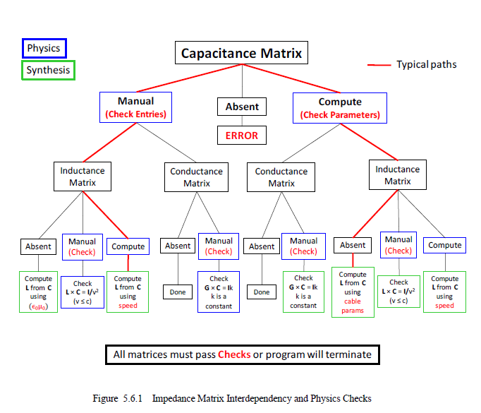
In addition, if MHARNESS is employed in EMA3D, then the segment ends must exist at the same physical location. If segment ends are separated by a physical distance, then these cannot be connected in a junction. An error message will result during the execution of EMA3D.
As discussed above, if a jacket is employed, then the cable is insulated from the surrounding material. However, this is not the case at the conductor ends. The ends will always be conductively connected to the surrounding material unless the ends terminate in a junction and a junction dielectric jacket is specified.
There are eight keywords associated with the cable segment impedance section of the MHARNESS input file. These keywords are listed below. • CAPACITANCE • CAPACITANCE COMPUTE • INDUCTANCE • INDUCTANCE COMPUTE • RESISTANCE • SKIN DEPTH RESISTANCE • CONDUCTANCE • CONDUCTANCE COMPUTE
The topics associated with these keywords are discussed in sections below in order of appearance in the list above.
EMA3D - © 2026 EMA, Inc. Unauthorized use, distribution, or duplication is prohibited.