Overbraid Transfer Impedance |
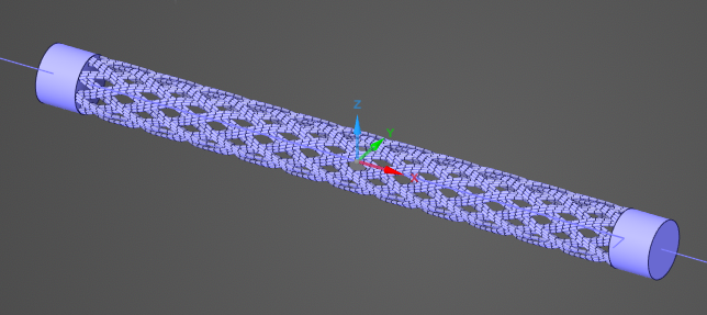
The Overbraid automatic workflow allows users to build the geometry of an overbraid and simulate its transfer impedance using only one click.
Note that the Mode parameter is set to Surface by default in order to support braid generation on lower-memory machines. For greatest accuracy, Body mode should be used whenever computational resources allow.
Additionally, note that this workflow should only be run in a new document. Unexpected behavior will occur if executed in a document with existing geometry or simulation objects.
Please allow several minutes for meshing to complete and analysis to begin.
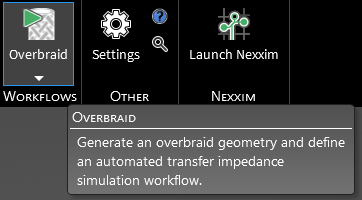
If the default selections are sufficient, simply click the
 Overbraid button in the Workflows section of the MHARNESS tab in the ribbon to start the simulation.
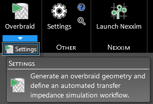
To run the Overbraid workflow with alternate settings, click the dropdown arrow beneath the
Overbraid button in the Workflows section of the EMA3D tab in the ribbon then click Settings.
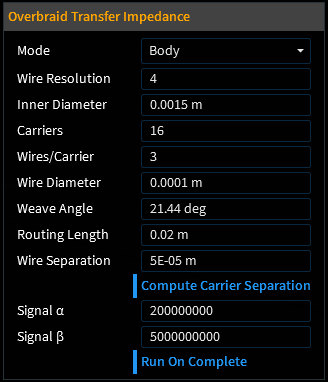
Expand Overbraid Transfer Impedance in the Properties Panel and then change the values as desired starting with the Mode parameter. A list of properties and their meanings are provided in the table below. Click OK
 to save and run.
Note: there are a few guidelines users should keep in mind in order to obtain physically meaningful results. They are:
For most braids, the mesh size should be no larger than 0.2~0.25x the carrier separation. This level is resolution is critical to accurately capture the inductive effects between carriers.
The lay length should ideally be at least 15~20x the diameter of the braid. For large braids, a shorter lay length may be necessary due to computational limitations.
The transfer impedance measurement becomes corrupted by resonances at high frequencies, so the simulation end time must be long enough to capture at least one to two decades below the first resonant mode. Its frequency can be calculated as one-fourth the speed of light divided by the lay length.
Entry | Meaning |
|---|---|
Mode | Whether the braid components should be modeled as bodies, surfaces, or lines (Body is the most accurate, but the default is set to Surface to accomodate lower-memory machines) |
Wire Resolution | Number of points (per mm) used to define the wire |
Inner Diameter | Inner diameter of the overbraid [m] |
Carriers | Number of carriers in the braid |
Wires/Carrier | Number of wires used for each carrier |
Wire Diameter | Diameter of wires [m] |
Weave Angle | Angle of weave in the braid [deg] |
Routing Length | Length of the overbraid [m] |
Carrier Resolution | Resolution used to simulate carriers |
Compute Carrier Separation | True/False - whether to automatically calculate the size of the gap between overlapping carriers (blue indicates True). This feature estimates carrier separation from other geometry parameters using a semi-empirical formula defined in Tyni 1976. This parameter should generally be set to true except in the following cases: Case 1: The user believes that the computed carrier separation isn't accurate for their particular braid and wants to input a more accurate value. Case 2: Even if the computed carrier separation is correct, the user might judge it to be too computationally prohibitive, since the mesh size should be no larger than 0.2~0.25x the carrier separation. If set to False, input the carrier separation [m]. |
Signal α | α for double exponential excitation equation |
Signal β | β for double exponential excitation equation |
Run on Complete |
True/False - whether to run the automatic workflow once OK |
Other Resources
EMA3D - © 2026 EMA, Inc. Unauthorized use, distribution, or duplication is prohibited.