Settings |
MHARNESS, EMA3D, and CHARGE currently permit users to adjust certain software and model parameters. How to change these parameters and what they mean are given below.
To open the settings / configuration options menu, click the Settings
 button under either the EMA3D or MHARNESS tab in the Ribbon within the Other section.
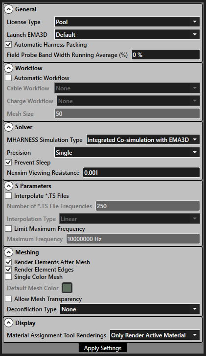
A list of EMA3D and MHARNESS options appear and are able to be adjusted. Those options are listed in the table below.
When finished editing Settings, click "Apply Settings" to save and exit.
Entry | Meaning |
|---|---|
License Type | Ansys HPC users can set this parameter to "Pool" or "Pack" based on their parallel license. Other users can ignore. |
Launch EMA3D | Whether to open the EMA3D and MHARNESS tabs, which will use an EMA3D license, every time Discovery is opened ("Always") or never when Discovery is opened ("Never"). "Default" is whichever of the two choices was selected during installation. Opening with the EMA3D icon will always open the EMA3D and MHARNESS tabs. |
Discovery Material Behavior | - |
Domain Buffer Value | - |
Automatic Harness Packing | Whether to pack the harness every time it is modified. Checking the box will pack the harness every time it is modified. Unchecking the box will only pack the harness during the harness export. This option is useful for harnesses with many cables that can take a longer time to pack. |
Field Probe Band Width Running Average | (CHECK THIS) This parameter changes the size of the bandwidth average. For calculating the electromagnetic fields and the transfer functions, EMA3D can perform a running bandwidth average on the field data. Then, EMA3D performs a Fast Fourier Transform of each location and averages the raw values together. Finally, EMA3D then performs another pass and "smooths" them out by averaging neighboring frequencies together with a sliding window. The default value is 0%, indicating that EMA3D does not by default compute a bandwidth average. |
Enable Beta Features | - |
Generate Charge Results in HDF5 Format | - |
Generate All Charge Simulation Files | - |
Entry | Meaning |
|---|---|
MHARNESS Simulation Type | "Integrated Co-simulation with EMA3D" will run MHARNESS and EMA3D coupled together. "Standalone MHARNESS Simulation" will only run the MHARNESS simulation. |
Precision | Whether the solver should use "Single" (32 bit numbers) or "Double" (64 bit numbers) precision. Double may take longer to run. |
Prevent Sleep | Checking the box will stop the computer from going into sleep mode while a simulation is running. |
Nexxim Viewing Resistance | Default value of 1 mΩ. In general, users should not and will not need to adjust this value. In MHARNESS Nexxim simulations, only voltages are directly measured. To obtain currents, a small "viewing" resistor with a value of 1 mΩ is inserted into the port. Importantly, the viewing resistance needs to be much lower (on the order of 100x) than the circuit impedance (most realistic circuits will already have a larger value). If the characteristic circuit impedance is on the order of 1 mΩ, users can reduce the viewing resistance value, though it can never be smaller than 1e-5 Ω. |
Use GPU Solver | - |
Entry | Meaning |
|---|---|
Interpolate *.TS Files | Whether to interpolate the output of the .TS file for S parameter simulations. |
Number of *.TS File Frequencies | Set the number of frequencies to output to the .TS file for S parameter simulations. Default value is 250. |
Interpolation Type | Whether to use linear or logarithmic interpolation between frequencies written to the .SNP file for S parameter simulations. |
Limit Maximum Frequency | Whether to limit the maximum frequency output of the .SNP file for S parameter simulations. |
Maximum Frequency | The greatest frequency that will be written to the .SNP file for S parameter simulations. All frequencies above this limit will not be output to the .SNP file and a new S parameter simulation will need to be run to generate S parameter results above this limit. |
Entry | Meaning |
|---|---|
Render Elements After Mesh | Toggles whether the mesh should be rendered after meshing is complete. |
Render Element Edges | Toggles whether rendering should show black edges around mesh elements. |
Single Color Mesh | Toggles whether mesh rendering colors should be based on the material color or if all geometry should be colored using Default Mesh Color. |
Default Mesh Color | The color of the mesh when material definitions are turned off or Single Color Mesh is selected. |
Allow Mesh Transparency | Toggles whether mesh elements can be drawn transparently (depending on the surface color), otherwise elements are always opaque. |
Deconfliction Type |
|
Line Deconfliction Type | - |
Autogenerate MHARNESS Variable Grid | - |
Save Mesh Externally | - |
Improved Surface Connectivity | Provides surface level post-processing for surface meshing that improves the connectivity within meshed surfaces by reducing the occurrence of gaps and misaligned surface elements.
|
Surface Interface Smoothing | Smooth meshed boundary of coincident surfaces by removing overhanging surface elements (re-mesh required for settings to apply).
|
Entry | Meaning |
|---|---|
Significant Figures Displayed | - |
Material Assignment Tool Renderings | - |
EMA3D – © 2026 EMA, Inc. Unauthorized use, distribution, or duplication is prohibited.