Source |
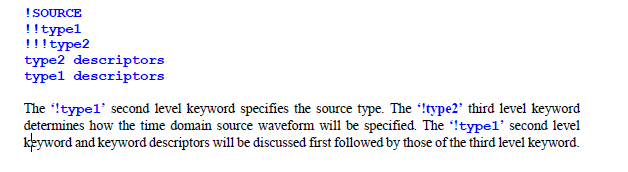
The general format of the SOURCE keyword is as follows.
When using a plane wave source, the incident direction must be defined along with the electric field polarization direction. Two angles are used to specify the incident direction. These angles (θ, φ) are defined in Figure 8.12.2.1.1(A). The variable, θ, is the incident direction polar angle and, φ, is the incident direction azimuthal angle. Like the incident vector, two angles are also used to specify the electric field polarization direction. These angles (α,β) are defined in Figure 8.12.2.1.1(B). The variable, α, is the polarization direction polar angle and, β, is the polarization direction azimuthal angle. When using plane wave illumination, the source is properly time retarded at various locations on the system to produce realistic results.
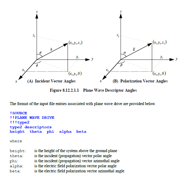
Note: The height of the system above the ground plane is used in the computation of the reflected wave. If the SEGMENT/SIMPLE combination pair is specified, then for any cable containing multiple conductors, all conductors are assigned the same specified height above the ground plane. If the SEGMENT/COMPLEX or the SEGMENT/COMPLEX2 combination pair were used to define all cable segments in the exposed system level, then the z-coordinates of the conductors in the various segments take precedence over the height specified here. The height parameter above is thus ignored.
EMA3D - © 2026 EMA, Inc. Unauthorized use, distribution, or duplication is prohibited.