Segment |
There are three second level keywords associated with the SEGMENT keyword. These keywords are listed and discussed below.
1) SIMPLE
2) COMPLEX
3) COMPLEX2
There are three possible formats for defining a simple segment. These formats are listed below.
1) Length specified
2) Coordinate ends specified
3) Descriptors exist for a shielding segment
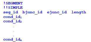
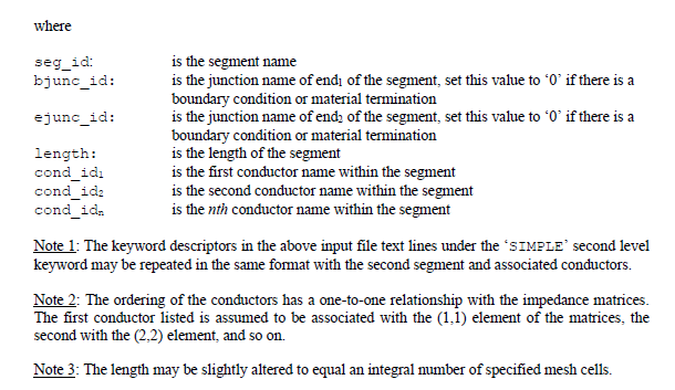
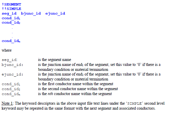
The length specified format can be used if the three-dimensional cross-sectional geometry does not need to be provided. This is the case if there is no plane wave excitation, if radiated fields are not to be computed, or if the impedance parameters/matrices are to be manually defined. The cross-sectional geometry is then implicit within the impedance information. The required input file text line format is:
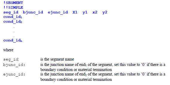
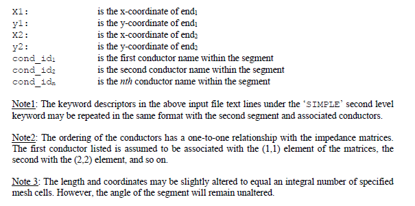
SIMPLE - Coordinate ends specified This format should be used only if plane wave excitation is specified, the impedance parameters/matrices are to be provided manually, and the cable system exists over a ground plane. The z-coordinate of the conductors is then provided by the height parameter within the plane wave source specification. The x and y-coordinate information is required to define the cable conductor orientation with respect to the incident and polarization parameters of the plane wave. The required input file text line format is:
SIMPLE - Descriptors exist for a Shielding Segment This format can be used when the geometric descriptors exist for an associated shielding segment and the impedance parameters/matrices for the shielded segment are to be provided manually. The required input file text line format is:
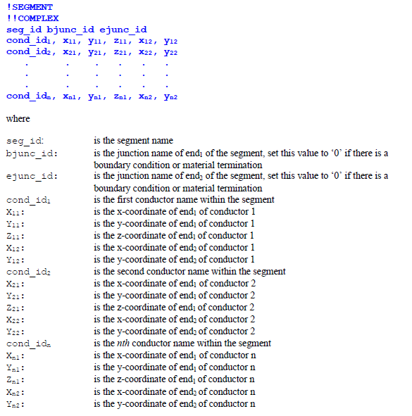
When the COMPLEX keyword is specified, the Cartesian coordinate ends of each conductor must be specified. Since the conductor is always considered parallel to the xy-plane, only one z-coordinate is to be provided. The required input file text line format is:
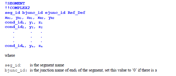
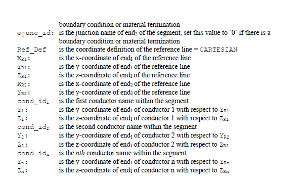
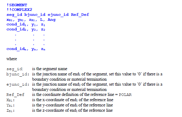
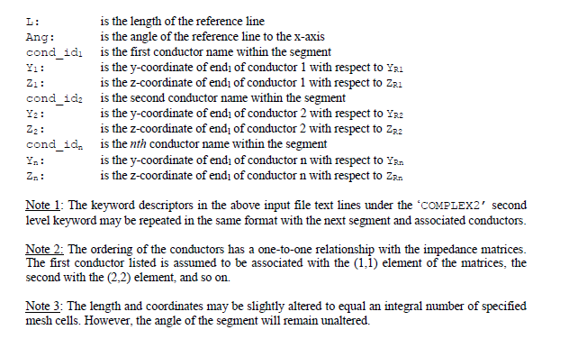
The COMPLEX2 keyword is used when utilizing a segment reference line description of a cable segment. This reference line provides the orientation of the cable segment. All conductors are then considered parallel to this line. To specify the reference line, the Cartesian coordinates defining the beginning (end1) must be provided. The far end of the line (end2) may be defined using Cartesian or polar coordinates. If Cartesian coordinates are specified, then the x and y coordinates of the far end of the line are to be provided. If polar coordinates are specified, then the length of the line and the angle the line makes with the x-axis are to be provided. Since the conductor is always considered parallel to the xy-plane, only one z-coordinate is to be provided.
When using the COMPLEX2 keyword all conductors are considered initially parallel to the x-axis. The beginning (end1) coordinates points are defined relative to the beginning reference line coordinates. These conductors will then be rotated to be oriented parallel to the reference line.
If a Cartesian coordinate system is used to define the reference line, then the required input file test line format is:
If a polar coordinate system is used to define the reference line, then the required input file text line format is
EMA3D - © 2026 EMA, Inc. Unauthorized use, distribution, or duplication is prohibited.