Boundary Conditions |
The ‘Section 10: Boundary Condition’ section of the input file contains two possible first level keywords. These keywords are listed and described below.
1) BOUNDARY CONDITION
2) JUNCTION BOUNDARY CONDITION
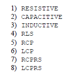
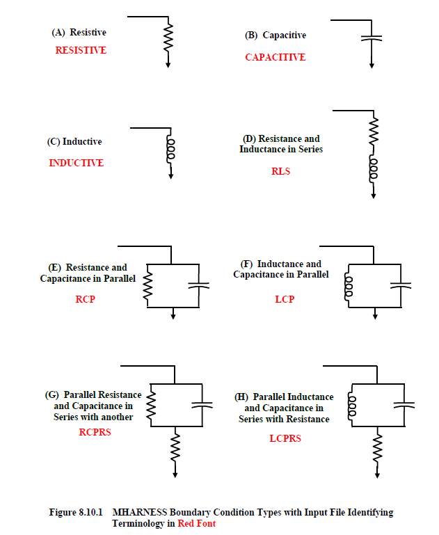
There are eight predefined lumped parameter boundary condition types that are available in
MHARNESS®. These boundary condition types were shown previously and are repeated below in Figure 8.10.1. The MHARNESS input file terminology identifying the boundary condition type is shown in red font.A boundary condition specifies a particular type of cable conductor termination. A nonzero conductance also defines another type for all conductors in a segment. These two paths, when defined on the same segment end, therefore conflict. However, if the conductance is large (associated with a material conductivity ≥ 100 Mhos/m), then the conductance can be eliminated, and the boundary condition employed. If the conductance is small (associated with a material conductivity less than 100 Mhos/m,), then an error message will result and the MHARNESS program terminated.
The eight second level keywords associated with the eight boundary condition types are listed below.
To terminate a conductor or shield in a short, or to leave either end floating, a resistive termination is required. For a short, let R = 0.0 ohms. To specify a floating or open circuit configuration, let R be a large number such as 1.0e8 ohms or higher. The default termination is an open circuit.
The input file format associated with each of the two first level keywords is provided in separate sections below, in order of appearance in the two lists provided above.
EMA3D - © 2026 EMA, Inc. Unauthorized use, distribution, or duplication is prohibited.