EMA3D 2026 R1 Overview |
This page contains a general overview of EMA3D 2026 R1
User interface, with the development of a new front-end
Harness module, with new features for cables definition
CHARGE module, featuring internal and surface charging capabilities
Mesher, with improved capabilities
Post-processing, with new plot tools and the implementation of automatic averaging and statistical functions. Implementation of EMA3D Connect.
The User interface of EMA3D has been implemented within the ANSYS CAE framework Discovery that is used as the front-end of the simulation tool.
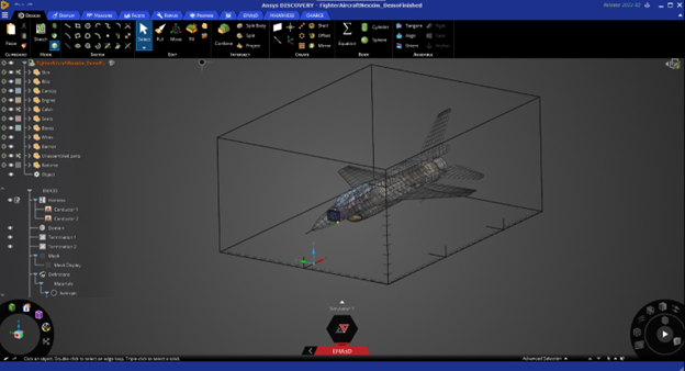
The front-end is divided into four main areas:
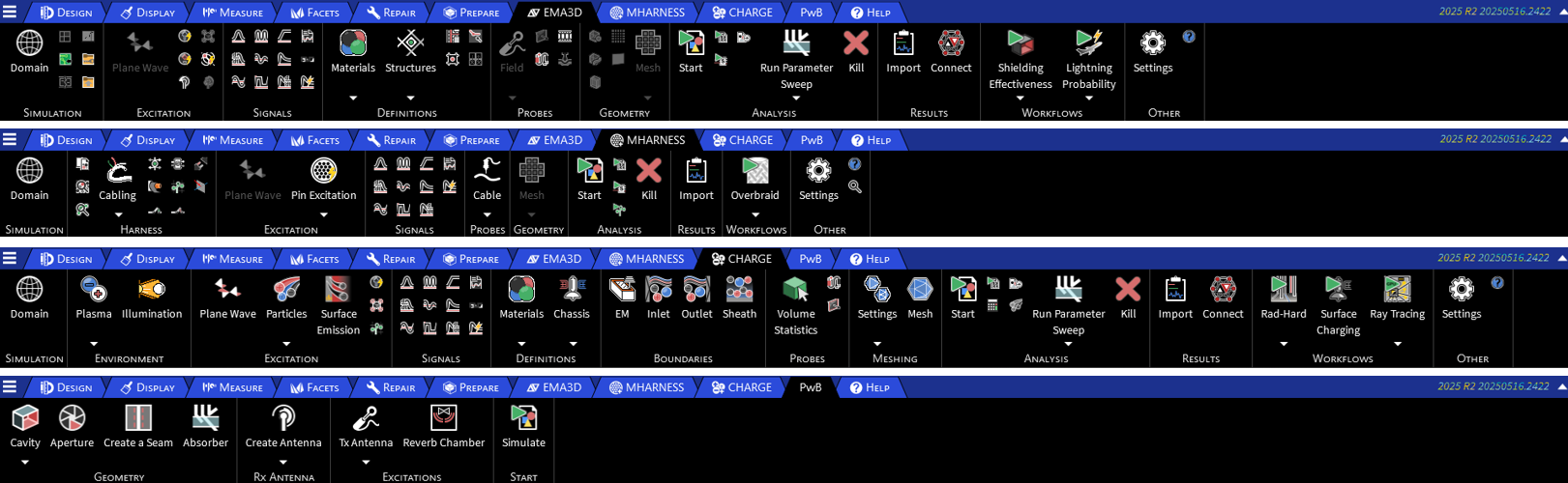
EMA3D, MHARNESS, CHARGE, abd PowerBalance Ribbons
Simulation Tree
Properties
Drawing area
The EMA3D, MHARNERSS, CHARGE and PowerBalance ribbons collect all the menus and tools for preparing the simulation model, for meshing and solving it, and for post-processing the results.
The input modeling data, the mesh models and the simulation results are stored in the “Simulation tree” from which they can be retrieved for inspection, editing, exporting and deleting.
Many actions are also accessible from the contextual menus available from each node of the “Simulation Tree”:
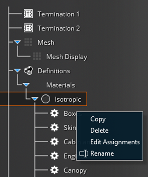
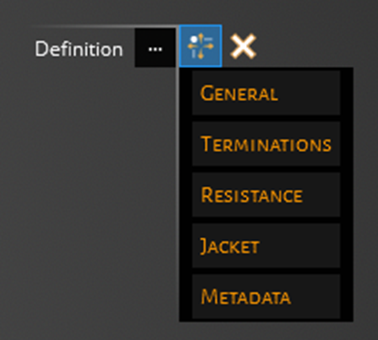
Once a contextual menu is selected, the drawing area and the “Properties” panel are updated to allow assigning the required settings.
Discovery functionalities allow the User to draw a geometrical model or to import it, besides that, powerful healing capabilities are available to correct geometrical inaccuracies such as overlapping, missed surfaces, non-contiguous surfaces, etc…

The MHARNESS module has been updated improving the procedure for harness modeling and introducing new capabilities such as the interactive editing of the harness cross-section.
The harness structure is stored under the Simulation tree and powerful editing capabilities are available to the User:
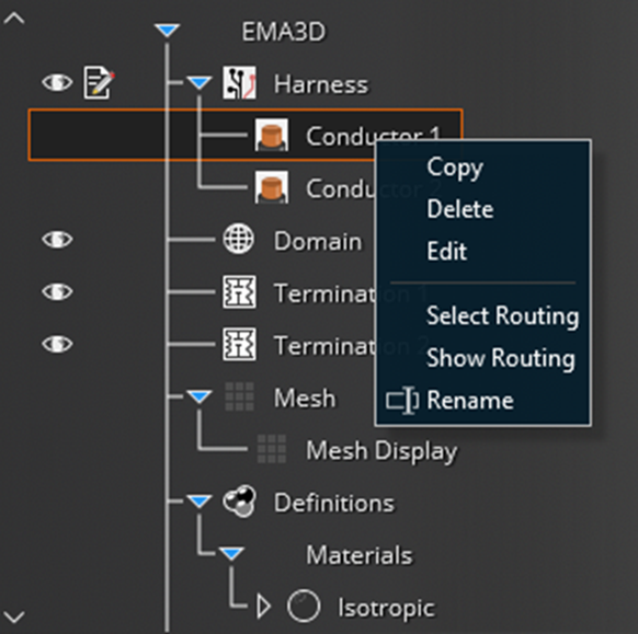
The topology of the harness can be visualized and the placement of each cable, within the harness cross-section, can be edited interactively:
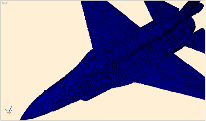
A new mesh engine has been developed and integrated into EMA3D. The mesh forms the basis for how the geometry is represented in the numerical simulation. The mesh engine generates a tartan, or structured, mesh of surfaces and lines for use in EMA3D’s finite difference time domain calculations. Mesh quality may include reliability, connectivity within a single surface, connectivity between adjacent surfaces, computational efficiency, and smoothness.
A reliable mesh engine should return a mesh for even poorly defined or oddly shaped surfaces. When the underlying geometry cannot be turned into a mesh, a reliable mesh engine should be able to exit smoothly. While geometry preparation is an important part of the CAE workflow, a reliable mesh engine attempts to support the application engineer by returning a reasonable mesh even when the CAE development time is limited.
A connected mesh avoids gaps in regions where material should be present. These gaps may occur within a given surface, or between adjacent surfaces that are otherwise connected. Adjacent surfaces are connected when they have equivalent boundary lines.
A computationally efficient mesh engine should require a time investment that is negligible compared to the overall CAE workflow. While the previous statement is not rigorously defined, the goal would be that the meshing process would not disrupt the productivity of the CAE engineer
A smooth mesh provides connectivity with the fewest possible number of mesh elements.
The EMA3D mesh engine algorithms attempt to incorporate all of these aspects of mesh quality, but priority is given in the following order: connectivity, reliability, computational efficiency, smoothness. Connectivity is crucial for reliable electromagnetic simulation results, so it is prioritized in the EMA3D mesh engine.
New post-processing capabilities have been integrated into EMA3D.
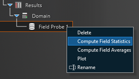
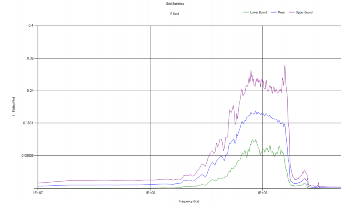
The output data produced by a field probe are stored in the node “Results” of the “Simulation Tree”, the contextual menu “Compute field statistics” calculates automatically the average value of the field and it bounds it between the minimum and maximum curves.
EMA3D integrates a new plot tool that provides great flexibility in the plot settings and improved capabilities in the generation of reports.
EMA3D Connect
EMA3D 2026 R1 integrates a newly developed tool called EMA3D Connect. EMA3D Connect streamlines data processing in electromagnetic simulation, enabling faster design decisions, real-time assessments, and advanced visualization through tools like ParaView and NVIDIA Omniverse.
EMA3D - © 2026 EMA, Inc. Unauthorized use, distribution, or duplication is prohibited.